
Designing a reinforced concrete column is a complex process, involving the interplay of various aspects that contribute to the overall strength, stability, and performance of the structure. The process extends beyond a mere calculation of forces and involves intricate considerations that must be accurately accounted for to ensure structural safety and durability. As the primary vertical load-bearing elements in a structure, columns play a critical role, withstanding not only gravity loads but also lateral forces due to wind or seismic activity.
To regulate this process and maintain high standards of safety and performance, professional engineers around the globe often turn to the provisions of ACI 318, a comprehensive standard developed by the American Concrete Institute (ACI) that outlines the requirements for concrete design and construction. The ACI 318 standard presents a wealth of technical requirements for column design that pertain to the material properties, load calculations, geometric constraints, reinforcement configuration, and other key factors.
In this article, we are discussing fifteen crucial aspects of column design as per ACI 318. These facets encompass a wide range of considerations – from material strengths to load determination, reinforcement detailing to fire resistance, and more. Each of these components plays a unique role in the column design process and offers insights into the meticulous detailing and careful planning that underpin the creation of robust, resilient structures.
By shedding light on these aspects, we aim to provide a comprehensive understanding of the intricacies involved in column design under ACI 318, underscoring the complexity of the process and the depth of understanding required to ensure the safe and efficient execution of such projects.
1. Material Strengths
Material strengths pertain to the compressive strength of the concrete (ƒ’c) and the yield strength of the steel (Fy) used in the design of the column. As per ACI 318-19, normal weight concrete should have a specified compressive strength (ƒ’c) not less than 2500 psi (17.2 MPa) and not more than 8000 psi (55 MPa) for routine structures. For high-strength concrete structures, the value of ƒ’c can be taken up to 22000 psi (150 MPa).
For reinforcement steel, the yield strength (Fy) used for design could be 60,000 psi (420 MPa) or 80,000 psi (550 MPa), corresponding to the ASTM designation of Grade 60 and Grade 80, respectively. It’s critical that these values are not arbitrarily chosen but are based on material tests, structural requirements, and local building codes.
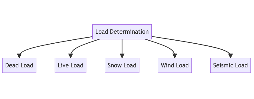
2. Load Determination
Load determination involves evaluating the forces a column is expected to resist. These loads include the dead loads, live loads, snow loads, wind loads, and earthquake loads as applicable. The dead load refers to the weight of the structure itself, including the building elements, fixed equipment, and other immovable components.
Live loads involve movable and changing factors such as people, furniture, and other temporary objects. ACI 318 refers to ASCE/SEI 7 “Minimum Design Loads for Buildings and Other Structures” for load determination. For instance, the minimum uniformly distributed live load requirement per ASCE/SEI 7-16 for an office building is 50 psf (pounds per square foot).
Snow loads are specified by local codes and can vary greatly depending on the geographical location. Wind loads depend on the wind speed, exposure category, building height, and other parameters, and can create lateral forces on a structure. Earthquake loads depend on the seismic activity of the location, and the building’s seismic design category. These lateral forces (wind and seismic) often govern the design of columns in high-rise structures.
3. Dimension of the Column
Dimensioning the column involves deciding on its cross-sectional shape and size. ACI 318 specifies that the least dimension of the column should not be less than 12 inches to ensure adequate confinement and ductility. While rectangular or square sections are common, circular sections are used for aesthetics or when high shear or torsional forces are present.
The dimensions are generally chosen based on the loading requirements, architectural needs, and practical considerations like formwork availability. The load-bearing capacity of the column depends on its cross-sectional area, so a column that needs to carry larger loads will need a larger cross-sectional area.
4. Reinforcement Ratio
The reinforcement ratio (ρ) is the ratio of the area of reinforcement (As) to the gross area of the column (Ag). ACI 318 stipulates that this ratio should not be less than 0.01 nor more than 0.08 for tied columns. For spiral columns, the reinforcement ratio should not be less than 0.01 nor more than 0.06.
This reinforcement ratio ensures that the column has sufficient steel to carry tension forces (since concrete is weak in tension) and provide adequate ductility while avoiding excess steel that would be difficult to place, cause congestion, or be cost-prohibitive.
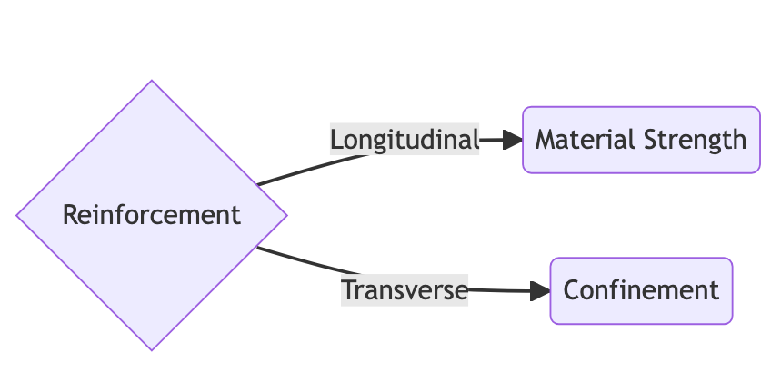
5. Longitudinal Reinforcement
Longitudinal reinforcement in columns primarily resists axial and bending forces. ACI 318 requires a minimum of four bars of longitudinal reinforcement for tied columns and six bars for spiral columns. For tied columns, this provides one bar for each corner of the column, ensuring a uniform distribution of forces. For circular columns, six bars provide a more even distribution around the circumference.
The total area of longitudinal reinforcement should be between 1% and 8% of the gross cross-sectional area of the column. This requirement ensures the column has enough ductility and strength to resist the imposed loads.
The clear distance between longitudinal bars should not be less than 1.5 times the bar diameter, nor less than 1.5 times the maximum size of the coarse aggregate. This prevents congestion and allows for proper concrete flow and consolidation during pouring.
These five aspects of column design are critical to ensure safety, efficiency, and longevity of the structure. They must always be guided by the comprehensive reading and understanding of the ACI 318 code, supported by sound engineering judgment. All designs should be carried out under the supervision of a qualified and licensed professional engineer.
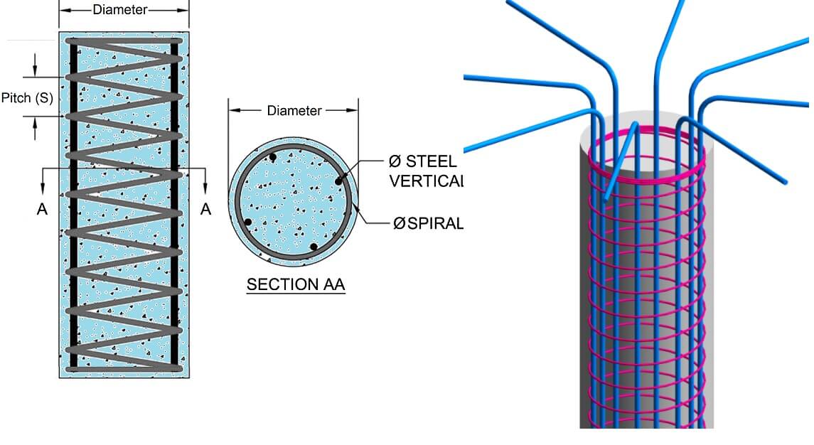
6. Transverse Reinforcement
Transverse reinforcement in columns, which is typically in the form of ties or spirals, serves multiple purposes such as confining the core concrete, preventing buckling of longitudinal bars, and increasing ductility.
In terms of ties, ACI 318-19 (Section 7.10.5.2) requires that the size of ties must be at least No. 3 for No. 10 and smaller longitudinal reinforcement bars, and at least No. 4 for No. 11 and larger bars. The spacing of ties should not exceed the smallest of 16 longitudinal bar diameters, 48 tie bar diameters, or the least column dimension.
For spiral columns, the reinforcement typically consists of a continuously wound reinforcement forming a helix around the longitudinal bars. ACI 318-19 (Section 18.7.5.2) specifies the clear spacing between spirals should not exceed 3 inches or be less than 1 inch. Spiral reinforcement provides superior confinement and ductility compared to tied columns, especially under seismic loading.
7. Spacing of Reinforcement
The spacing between the reinforcement bars is important to ensure that the concrete can be properly placed and compacted. As per ACI 318-19 (Section 7.6.5), the minimum clear spacing between parallel bars in a layer should not be less than the nominal diameter of the bar, 1.33 times the maximum size of the coarse aggregate, or 1 inch.
This clear spacing allows for the passage of the vibrating needle during the compaction process, ensuring that the concrete can fully envelop the steel reinforcement, thereby providing the required bond strength and protection from corrosion.
8. Lateral Support
Columns need lateral support to prevent the buckling of the longitudinal reinforcement under compression. For columns, ties or spirals can provide the necessary lateral support. As per ACI 318-19 (Section 7.10.5.1), the longitudinal bars should be laterally supported by the corner ties, and the unsupported length of these bars should not exceed 48 times the bar diameter.
The correct detailing and placement of lateral support are crucial to the stability and performance of the column, particularly under seismic loads.
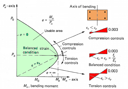
9. Column Interaction Diagram
The interaction diagram depicts the axial force-bending moment relationship for a column cross-section, showing the various combinations of axial load and bending moment that the column can resist. This is used in the design of columns subjected to axial load and moment simultaneously.
The interaction diagram is constructed based on the provisions of ACI 318-19, taking into account the strain distribution in the column section under various loading conditions. The generation of the interaction diagram involves calculating the axial load capacity and moment capacity at various strain conditions, and plotting them in a P-M (axial force – moment) graph. The interaction diagram is essential to verify the column design and ensure that it has sufficient strength and ductility under the expected loads.
10. Slenderness Effects
Slenderness effects become significant in slender columns, where the column’s height significantly exceeds its least lateral dimension. These columns are subject to additional stresses due to buckling, and these effects need to be taken into account in their design.
ACI 318-19 addresses slender columns in Chapter 6. As per the code, the slenderness effect is considered significant if the column’s effective length ratio (kl/r) exceeds 22 for tied columns or 34 for spiral columns, where k is the effective length factor, l is the unbraced length of the column, and r is the radius of gyration of the column.
In such cases, the column is designed considering the additional moments induced by second-order effects (P-Delta effects), which are calculated using either the moment magnification method or the second-order analysis method as per ACI 318.
This set of aspects, like the previous, underscores the importance of a careful and comprehensive approach to column design, grounded in a thorough understanding of the ACI 318 code. A qualified and licensed professional engineer should always oversee the design process.
11. Confinement Requirements
Confinement in the context of column design refers to the practice of enclosing the concrete core of a column within closely spaced transverse reinforcement to enhance the ductility and the ultimate load capacity of the column, especially under axial load and bending. The confined core provides a significant portion of the column’s strength and deformation capacity, particularly under seismic loading.
ACI 318-19 (Section 18.7.5.2) mandates the confinement requirements for columns. The code prescribes that the core of a spiral column should be confined with spiral reinforcement not smaller than No. 3 at a pitch (vertical distance between turns) not exceeding 3 inches and not less than 1 inch.
12. Fire Resistance
Designing for fire resistance is crucial in protecting the structural integrity of a building in the event of a fire. As per ACI 318-19 (Section 7.7), the fire resistance of a concrete column is primarily a function of the column size, the amount and distribution of reinforcing steel, and the concrete cover over the reinforcement.
Columns must satisfy minimum dimension and cover requirements to ensure an adequate fire resistance rating. For instance, a 3-hour fire resistance rating may require a cover of 2 inches for No. 6 bars and smaller, and 2.5 inches for larger bars, along with other requirements based on the detailing of the reinforcement.
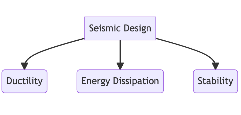
13. Seismic Design
For structures located in areas of high seismic risk, the design and detailing of columns must comply with more stringent requirements, which are covered in Chapter 18 of ACI 318-19. These provisions enhance the column’s ability to deform (ductility) and dissipate energy without catastrophic loss of strength or stability during an earthquake.
For instance, ACI 318-19 requires that boundary elements (highly confined areas) be provided in certain regions of columns that are part of special moment frames and are subject to large inelastic deformations. This enhances the ductility and strength of the column under seismic loads.
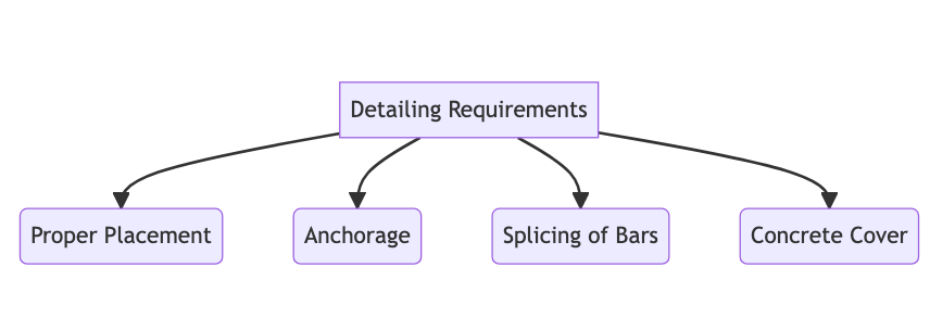
14. Detailing Requirements
Detailing of reinforcement involves the correct placement, anchorage, and splicing of bars, and providing the appropriate cover. ACI 318-19 (Chapter 25) includes specific provisions for reinforcement detailing to ensure structural integrity, constructability, and durability.
The code specifies the minimum concrete cover for reinforcement based on the exposure conditions and the size of the reinforcement. For example, for concrete cast against and permanently exposed to the ground, the minimum cover is 3 inches, whereas for reinforcement in an interior environment, the minimum cover could be as low as 0.75 inches for No. 14 and No. 18 bars.
15. Consideration of Combined Stresses
In real-world conditions, a column is subjected to both axial forces and bending moments. Therefore, column design should involve the consideration of these combined stresses to ensure structural safety. This is captured in the interaction diagram, which portrays the various combinations of axial load and bending moment that the column can resist.
The axial load creates a uniform compressive stress across the column’s cross-section, whereas the bending moment induces a variable stress, causing tension on one side of the column and compression on the other. The combination of these stresses and their interaction forms the basis of the column design, ensuring it can safely resist the expected loads.
As always, these factors underline the need for a comprehensive, meticulous approach to column design, firmly rooted in an understanding of the ACI 318 code. The design should always be supervised by a qualified and licensed professional engineer.
FAQ’s
What is the minimum dimension for a column according to ACI 318?
ACI 318 specifies that the least dimension of the column should not be less than 12 inches. This ensures adequate confinement and ductility in the column.
What is the reinforcement ratio in column design?
The reinforcement ratio (ρ) is the ratio of the area of reinforcement (As) to the gross area of the column (Ag). ACI 318 stipulates this ratio should be between 0.01 and 0.08 for tied columns and between 0.01 and 0.06 for spiral columns.
How are slenderness effects handled in column design as per ACI 318?
ACI 318 addresses the slenderness effects in columns. If the column’s effective length ratio exceeds 22 for tied columns or 34 for spiral columns, the column design should consider the additional moments induced by second-order effects (P-Delta effects).
What is the role of confinement in column design according to ACI 318?
Confinement refers to enclosing the concrete core of a column within closely spaced transverse reinforcement. This enhances the ductility and the ultimate load capacity of the column, especially under axial load and bending. ACI 318 mandates specific confinement requirements for columns.
What is an interaction diagram in column design?
The interaction diagram in column design depicts the axial force-bending moment relationship for a column cross-section, showing the various combinations of axial load and bending moment that the column can resist.
What are the lateral support requirements for columns as per ACI 318?
Lateral support in columns prevents buckling of the longitudinal reinforcement under compression. As per ACI 318, longitudinal bars should be laterally supported by the corner ties, and the unsupported length of these bars should not exceed 48 times the bar diameter.
How does ACI 318 address the spacing of reinforcement in column design?
ACI 318 specifies that the minimum clear spacing between parallel bars in a layer should not be less than the nominal diameter of the bar, 1.33 times the maximum size of the coarse aggregate, or 1 inch. This provision ensures proper concrete placement and compaction.
What is the significance of the transverse reinforcement in column design according to ACI 318?
Transverse reinforcement, typically in the form of ties or spirals, provides confinement to the concrete core, prevents buckling of longitudinal bars, and increases ductility. ACI 318 specifies the requirements for size and spacing of these transverse reinforcements in column design.
Read More
2 thoughts on “15 Essential Aspects of Exceptional Column Design as per ACI-318”