
If you work with beams, you often need to draw a Shear Force Diagram (SFD) and a Bending Moment Diagram (BMD). These diagrams tell you where the beam feels the highest shear and the highest bending. They help you pick a safe size and check deflection limits. For this a Shear Force and Bending Moment Diagram Calculator is needed.
Below you’ll find a guide and a free Shear Force and Bending Moment Diagram Calculator that works for single and multi-span beams, with point loads, UDL, UVL, and point moments. It also supports roller, pinned, fixed supports, and internal hinges. You can use US units (kip, ft-lb) or metric in Shear Force and Bending Moment Diagram Calculator.
What is a Shear Force Diagram (SFD)?
The shear force at a section is the vertical force that tries to slide one part of the beam past the other. You can draw the shear force diagram using the Shear Force and Bending Moment Diagram Calculator given below.
The SFD shows how this shear changes along the length. Key ideas:
- A point load causes a sudden jump in the SFD.
- A UDL (uniformly distributed load) makes the SFD slope in a straight line.
- A UVL (triangular or trapezoidal load) makes the SFD curve change linearly.
- Where the SFD crosses zero, the BMD often reaches a maximum or minimum.
What is a Bending Moment Diagram (BMD)?
The bending moment is the internal moment that bends the beam.
The BMD shows how this moment varies with x. You can draw the bending moment diagram using the Shear Force and Bending Moment Diagram Calculator given below.
Basic rules:
- The slope of the BMD equals the shear: if shear is positive, the moment rises.
- A point moment causes an instant jump in the BMD at the load point.
- With UDL, the BMD is a smooth curve (parabolic).
- With UVL, the BMD curvature changes gradually.
Online calculator for drawing SFD and BMD
Hand work is slow, and mistakes are easy when you have two-span or continuous beams with mixed loads. The calculator:
- handles point load at midspan, UDL, UVL (triangular/trapezoidal), and point moments together,
- lets you add roller, pinned, fixed supports, and internal hinge (moment release),
- draws a loading diagram, SFD, and BMD in one view,
- reports maximum shear and maximum bending moment,
- supports kN–m and kip–ft (US units).
How to use the Shear Force and Bending Moment Diagram Calculator
Step 1: Define Beam Spans and Units
Enter the number of spans and their lengths. For example, a two-span beam with lengths of 5 m and 4 m. Choose units: meters/kN or feet/kips.
Step 2: Add Supports
Select supports at the ends and in between. Options include:
- Pinned support: resists vertical force but allows rotation.
- Roller support: same as pinned but allows horizontal movement.
- Fixed support: resists vertical force and moment.
- Internal hinge: allows rotation at that point, often used in continuous beams.
Step 3: Apply Loads
Enter the type, magnitude, and location of loads:
- Point load at any distance.
- Uniformly distributed load (UDL) across a span or part of a span.
- Uniformly varying load (UVL) rising or falling in intensity.
- Point moment applied at a section.
The loading diagram updates instantly to show all forces clearly.
Step 4: Generate Diagrams
The tool calculates support reactions, then plots:
- Loading diagram (clean arrows and values).
- SFD (jumps, slopes, and curves).
- BMD (straight lines, parabolas, or other curves).
Step 5: Read Maxima
Finally, the tool gives maximum shear force and maximum bending moment with their x-locations. These are the values engineers use to size beams.
Worked Examples
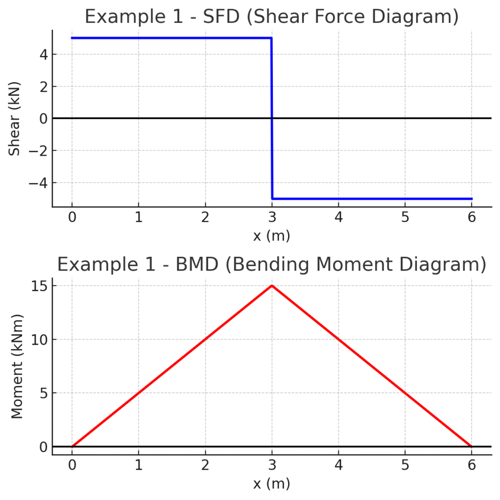
Example 1: Point Load at Midspan
A 6 m simply supported beam with a 10 kN load at midspan.
- Reactions: 5 kN each at supports.
- SFD: rises to +5, drops to -5 at the load.
- BMD: triangular with maximum 15 kNm at midspan.
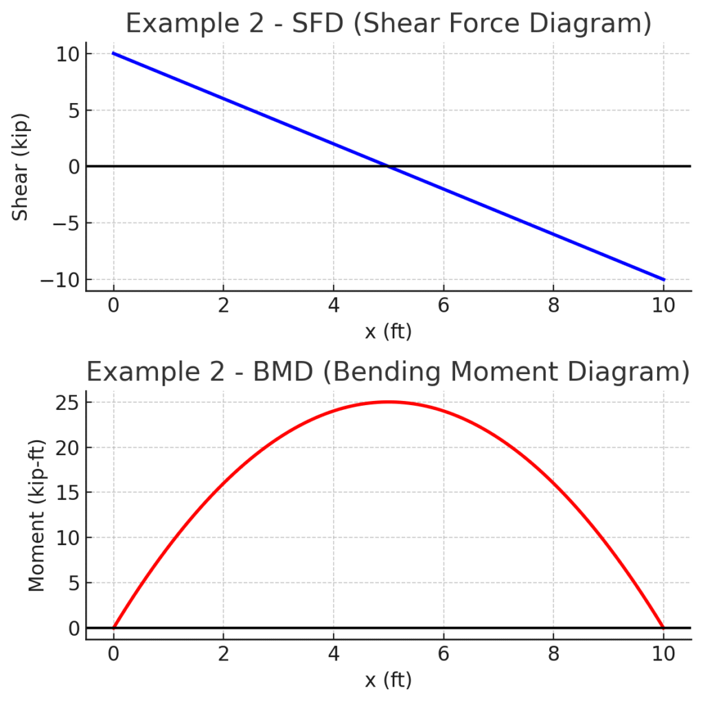
Example 2: UDL Across the Span
A 10 ft simply supported beam with a 2 kip/ft UDL.
- Reactions: 10 kip each.
- SFD: straight line from +10 to -10.
- BMD: parabolic, maximum 50 kip-ft at midspan.
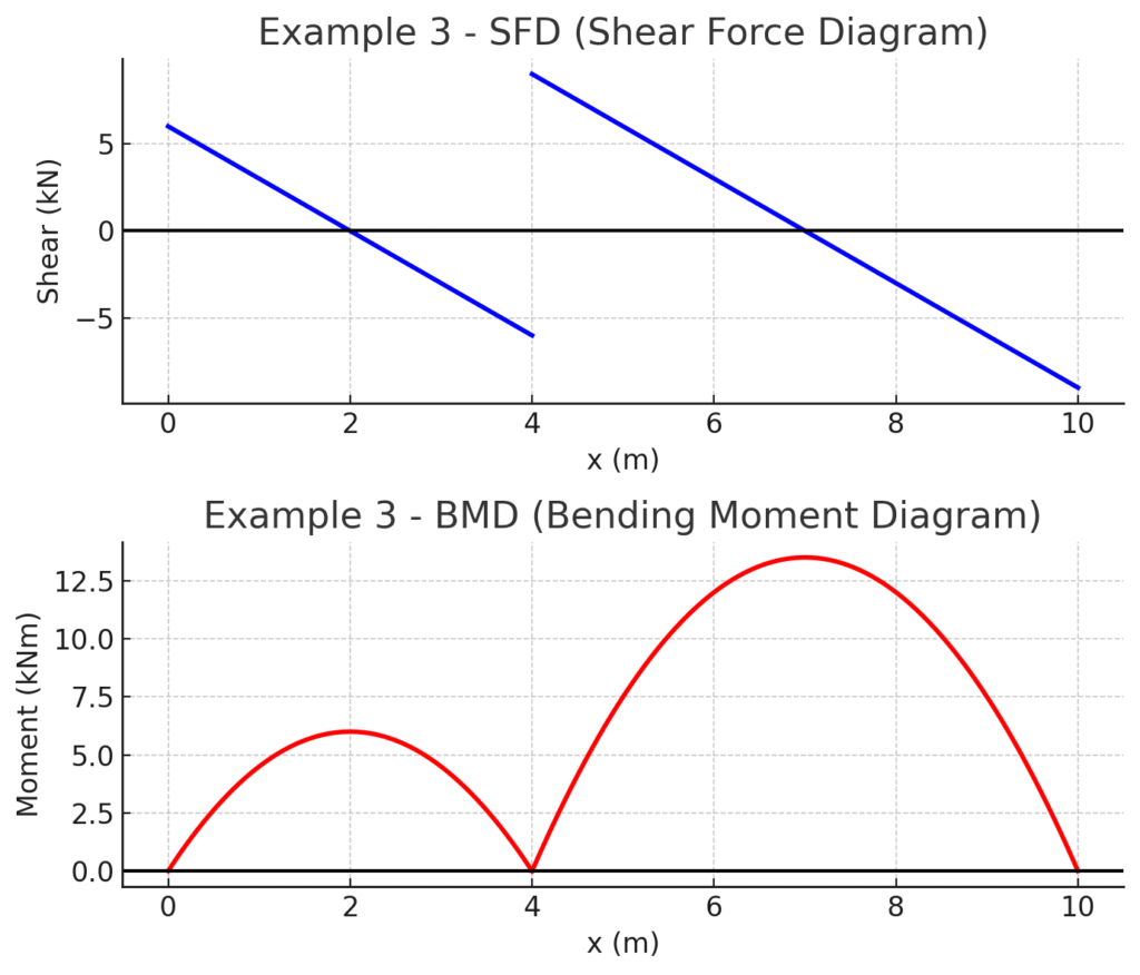
Example 3: Two-Span Continuous Beam
Spans: 4 m + 6 m, UDL of 3 kN/m. Internal hinge at 4 m.
- SFD: slope under UDL, hinge releases moment.
- BMD: zero moment at hinge, peaks in each span.
FAQ’s
What is the sign convention for SFD/BMD?
Use one convention consistently. For example: upward reactions positive, downward loads positive, sagging moment positive and hogging moment negative.
Where is the maximum bending moment occurs in the beams?
Often near where shear = 0. The calculator can highlight the x-location.
Can I use the calculator for cantilever beams?
Yes. Use a fixed support at the left (or right) and add your loads. The SFD and BMD will match the classic shapes.
Read More